The AlterTM
Introduction
Turing Machines are well known as an abstract model of computability. A Turing Machine (TM) is just a program written in a simple language with only one instruction type, executed by a finite-state machine with read-write access to a bidirectional "tape". A Universal TM is one that can simulate any TM by giving it, as input, the program for the TM being simulated and initial tape data, if any. The operation of a Universal TM has often been replicated in hardware or modern software.
The AlterTM web page is a simulation of a hardware implementation of a Universal TM. It looks like a classic MITS Altair 8800 hobbyist computer, with some panel modifications to suit its new purpose.
The Altair 8800, based on earlier 680 and 6800 models, was implemented with integrated logic chips. It had an Intel 8080 CPU with a machine language employing 78 instructions. It included 256 8-bit words of random-access memory, extendible to 64K.
The AlterTM provides only the single instruction type characteristic of Turing Machines. A true Turing machine has an unbounded tape, but the AlterTM shares the Altair's limited memory of 256 8-bit words. It also shares the need to load programs into its memory via the switch panel or some accessory, in this case the host browser.
The HTML and Javascript implementation of the AlterTM is nothing to boast about, but it might be interesting to look at the technique for designing the TM program used for the 1-D Life example, explained on the separate page 1DLifeStates. Briefly, the idea is to collapse the 28 states into five parameterized state types.
Front Panel Switches and Lights
The AlterTM control panel has two rows of red readout lights and two rows of toggle switches. The white toggle switches are used to enter one 8-bit word of data that will be used as either (1) a memory address that will appear in the Address readouts in the lower row, or (2) a word of data that will appear in the Data readouts in the upper row.
| D15-D8 | D7-D0 |
| A15-A8 | A7-A0 |
| red switches | white switches |
| control toggles | |
Currently, the red toggle switches are not used, and neither is the upper word of address readouts A8-A15, since only 256 words of memory are presently supported. Some text windows and dropdown menus have been added to the panel to simplify operation.
On the web page, switches are operated by clicking on them. Address switches toggle up and down alternately when clicked. Control toggles act more like buttons than switches, because they spring back to the middle when released. Most controls have two functions, according to the labels above and below the switch. Click on the label rather than the switch, to indicate which function is desired. The various functions of the control switches will be described below, after we have explained how Turing Machines are represented in the AlterTM.
Turing Machine Representation
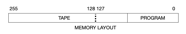
The Tape
In the AlterTM memory, the lowest word addresses, up to a maximum of 127, are available for
the TM program. Addresses above the end of the program are usable for data.
Note that the data/program boundary depends on the length of the program.
Under program control, the tape head can travel in either
direction from an initial position in the data area.
If the head runs into the program below or the end of memory above,
the program halts.
The tape head location is just a bit address, which is the combination of the current word address and a bit position 0-7. The current word address is always shown on the Address readouts A7-A0.
The data readouts D0-D15 act as a movable window that always shows the addressed word with the head on the right, in D0-D7. The head bit position is indicated with a green underline in that word. When the head moves across a word boundary, the data display window shifts to keep it on the right.
When memory or address words are displayed in the readouts, the low-order bit is the rightmost bit, as usual for numbers written in binary notation. Bits within a word are numbered accordingly: bit 0 is the rightmost bit and bit 7 is the leftmost.
When word n is on the right in D0-D7 on the Data display, word n + 1 is on its left in D8-D15. This is natural because the high order bit of word n will be next to the low order bit of word n + 1.
The Program
A TM program is a finite-state machine that reads an input bit from the tape position under the head, rewrites the bit that tape position, moves the head one step left or right, and changes the state. It takes two instructions to encode the state: one specifying the action if it has read a 0-bit, and the other for a 1-bit. In the AlterTM, each state specification has the two-word form:
| 1 read | 0 read | ||||
| w | d | state | w | d | state |
In each instruction, W is a bit value to be written, D encodes the direction the head moves, and the number of the next state fills out the rest of the word. The directions are 0 for right, or decreasing address, and 1 for left, or increasing address.
The state number is half the instruction address, and that address is always even. The six-bit state field has room to specify 64 states occupying 128 words. State 0 is always taken as the initial state.
Here is a simple example-- a program that writes two 1s on the tape, regardless of what was there, and stops.
| 1 | 1 | 000010 | 1 | 1 | 000010 | 1 | 1 | 000001 | 1 | 1 | 000001 |
The initial state 0, with instructions in words 0 and 1, writes 1, moves the head one bit left, and enters state 1, at word address 2. State 1 does the same and tries to enter state 2, at word address 4. But the program has length 4, which only includes words 0-3, so the TM halts because state 2 does not exist.
How does the AlterTM know where the program ends and the tape begins? Good question. See the discussion below on the LOAD function.
Operation
Entering Data With Toggles
The EXAMINE and DEPOSIT functions work just as in the Atair 8800. EXAMINE sets the current address from the white switches, and updates the data display accordinly. DEPOSIT sets the memory data from the white switches into the currently addressed word.
In both cases, after the action, the displayed data is the contents of the word at the displayed address.
EXAMINE NEXT and PREV just increment or decrement the address by one, respectively, and update the data readout.
DEPOSIT NEXT stores the white switch setting into the next word after incrementing the address.
Note that these functions work anywhere in memory, whether within the tape or program areas.
TAPE is a short cut to move the head to address 128. This is handy to help put the head in a convenient initial position for the program, and for entering input data. RESET sets the address to 0; TAPE sets the address to 128. CLEAR is a RESET that also zeroes out the data memory.
Using LOAD
The LOAD function has two related uses. One is to load a complete program from an externally prepared list, analogous to an auxiliary device. When a program is loaded this way, the AlterTM automatically identifies the split between the program and the tape area.
The other use of the LOAD function is to specify the length of a program being entered manually. This serves to determine the beginning of the tape area.
Either way, the LOAD function puts up an HTML dialog asking for a list of numbers. The list that appears initially is the sample program currently selected with the AUX dropdown. The samples include the 3- and 4-state Busy Beaver TMs and a single evolution of a One-Dimensional Life cellular automaton, as described elsewhere on this website. The 1D-Life evolution program is a scan from left to right, so be sure that the head is initially to the left of the starting input pattern, using EXAMINE if necessary, or TAPE if convenient.
If only one number is entered in the LOAD dialog, it is interpreted as the length of the program in words (twice the number of states). If a list of two or more (decimal) numbers is entered, the numbers are converted to binary and interpreted as instructions, listed in increasing address order.
A program instruction list can be copied from a text file and pasted into the dialog, to load the user's TM program.
Using the simple four-instruction example above, the number 4 alone would specify the length of the program. If the entire program is to be loaded at once, the appropriate list is:
(When converting an instruction from binary to decimal for this purpose, it helps to remember that 1-bits at positions 7 and 6 contribute 128 and 64, respectively.) Note that the instruction list is ordered from low to high word addresses, the reverse of the convention in the memory picture above.
Running a Program
Running a program is easy. Set the word address to the place where data processing should begin, using EXAMINE or TAPE, then hit RUN. Execution begins in state 0, and continues executing at two instructions per second. This rate is deliberately slow enough to make a good show.
The CLOCK dropdown menu offers a choice of execution speeds from 2 to 32 instructions per second. Without this artificial speed limiter, the program would run to halt instantly, if it was not caught in a loop. If it is in a loop, hit STOP to interrupt it. Normal or forced halts light the HALT readout.
A program can also be executed one state transition at a time, with the STEP function.
Other Panel Features
There are small windows that do not appear on the Altair, but are included for convenience in the AlterTM. They show the current value, in decimal, of the displayed Data word, its Address, and the program counter PC, which is just the address of the current instruction. Half that number is the current state.
The PROTECTED/UNPROTECTED and ON/OFF controls appear on the Altair but are not used in the AlterTM.